Even with a proper RGB SCART cable to suit your machine, you may have problems with display ghosting when trying to use the RGB output of the system. This is because the 128 Spectrums don’t provide a proper signal that can be used as the SCART blanking signal.
The following sections detail the modifications needed so that the correct blanking voltage is made available on pin 1 of the RGB socket. On 128 and grey +2’s, this pin carries composite video out, so be sure that you no longer wish to use this output before proceeding.
Tools required:
- Soldering iron
- Solder wick / desoldering pump
NOTE: This modification in all case involves routing the 12v power rail through a suitable resistor to provide the correct blanking voltage.
Take care and ensure that the 12v rail is not accidentally connected to any other part of the circuitry – if done incorrectly your ULA or ASIC may be irreparably damaged.
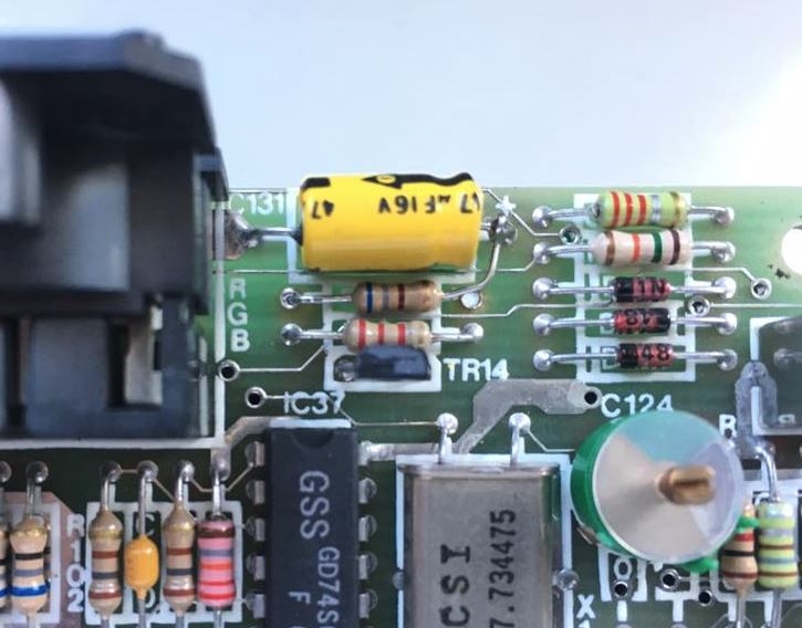
Spectrum 128
Remove R134, and replace with a 680 ohm resistor in the left through hole – do not replace the right end in the usual position but connect it to right side of C131 (immediately north of R134) which carries 12v.
Spectrum +2 (Grey model)
Remove the LK4 jumper and replace in the LK2 position, and replace R9 (1K) with a 680 ohm resistor.
Spectrum +2A (Black +2) / +3 Models
Replace R44 with a 680 ohm resistor, or piggyback a 1Kohm resistor over the existing one.
