
This modification is for Datasette recorders with the PCB marked Part Number 377 on the front (non green) of the PCB.

You will need:
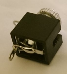
- 1 x 3.5mm mono socket.
- 1 x on/off switch (optional)
- Wire
- Soldering Iron and Solder
First you need to locate where the audio input wire needs to be soldered on. This is to pin 5 of the LA6324 chip. I have marked it on this picture.

Next you need to locate a good place for the Ground wire. I found an empty hole on the PCB marked as 307 on the front of the PCB. This should give you a good place to solder the wire in.

Next you need to connect the ground wire to the 3.5mm Socket.
The audio input pins need to be wired together. You can either thread the audio in wire through the holes and then solder the wire to the pins or do what I do.


Next wire the audio input wire from the socket to the middle pin on the switch and the audio input from the PCB to the other pin on the switch.

Drill two 6mm holes in the back of the +2 case and thread the switch and the audio socket through and reseat the datasette mechanism.

Reassemble your +2 and away you go.